Visual Crash Studio (VCS) is a unique tool for crash analysis at the pre-design stage of vehicle development. The advantage of the VCS software is the possibility of making independent calculations at various stages of the modeling. Initial analyses refer to the cross-sectional level of the model. Subsequent calculations can be performed as each sub-assembly of the structure is developed. In the case of a simple model, calculation time should not exceed several dozen seconds. For complex design, the time required for calculation should not exceed several minutes. In consequence, the Visual Crash Studio environment enables constant and quick verification of the model until the final simulation of the complete assembly is achieved.
VCS specific workflow characterized by a simplified modeling method assures easy application of design modifications. The approach of parallel modeling and analysis is most suitable for the VCS workflow. The efficiency of such a line of a design process is insured due to the short computation time (seconds to minutes compared to hours in FE solvers). In consequence, VCS is recommended to be used in the pre-design stage of product development, where the possibility of fast verifications and adjustments of the designed structure is essential.
Visual Crash Studio does not compete with FE methodology solvers but complements them. It gives the possibility to develop, verify and optimize a vehicle concept with accurate crash analysis at the early stage of the structure development process, thus avoiding time and cost–consuming major modifications in later stages of vehicle development. VCS calculation model can emerge from scratch or be based on detailed data obtained from FEM solvers.
CRASH CALCULATIONS IN SECONDS? – IT’S POSSIBLE!
Constantly growing crash safety requirements enforce the implementation of various strategies in vehicle body design. Test procedures involve laboratory experiments as well as numerical simulations.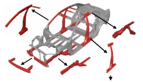 The process of structure development is time and cost-consuming. Therefore, more effective procedures are sought.
The possibility of studying the influence of various parameters on crushing response is a tempting perspective.
The Macro Element Method (MEM) perfectly fits crash performance analysis and optimization purposes and can be treated as a complement to the finite element methods. The macro element approach is advantageous in predicting the crushing response of thin-walled members of various ductile isotropic materials. Implementation of MEM gives the highest efficiency at the early stages of vehicle development.
The process of structure development is time and cost-consuming. Therefore, more effective procedures are sought.
The possibility of studying the influence of various parameters on crushing response is a tempting perspective.
The Macro Element Method (MEM) perfectly fits crash performance analysis and optimization purposes and can be treated as a complement to the finite element methods. The macro element approach is advantageous in predicting the crushing response of thin-walled members of various ductile isotropic materials. Implementation of MEM gives the highest efficiency at the early stages of vehicle development.
 The Macro Element Method is based on simplified modeling. The concept of Super Folding Element at the cross-sectional level and Super Beam Element in the case of a 3D structure enables the creation of simplified models of various design concepts.
The MEM calculation process comes with a low computational cost. Calculation time does not exceed several seconds in case of various cross-sections and several minutes in complex beam structures.
The method guarantees that analysis is performed in a reasonable amount of time. The results obtained from the calculation can be compared with laboratory tests and FE calculations. Most significant for the fast analysis and optimization purpose is the possibility of easy modification of a simplified structure (coordinates of points, plate thickness, assigned material).
The Macro Element Method is based on simplified modeling. The concept of Super Folding Element at the cross-sectional level and Super Beam Element in the case of a 3D structure enables the creation of simplified models of various design concepts.
The MEM calculation process comes with a low computational cost. Calculation time does not exceed several seconds in case of various cross-sections and several minutes in complex beam structures.
The method guarantees that analysis is performed in a reasonable amount of time. The results obtained from the calculation can be compared with laboratory tests and FE calculations. Most significant for the fast analysis and optimization purpose is the possibility of easy modification of a simplified structure (coordinates of points, plate thickness, assigned material).
USE CASE EXAMPLE – B PILLAR
One of the practical examples of using Visual Crash Studio can be the strength testing of the B-Pillar, where the bending response of the assembly is checked. One of the most significant challenges faced by the engineers is to reduce the mass of the part and at the same time fulfill crash requirements. The MEM can be implemented in such a design process on two levels.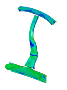
FE model
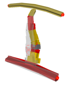
MEM model
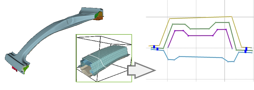 On the level of cross-sections, bending moment analysis for various materials and geometry variants can be performed. The simplicity of the model enables quick and easy modification of the geometry. Each plate of a cross-section can have individual properties assigned, which allows testing of various thicknesses and materials.
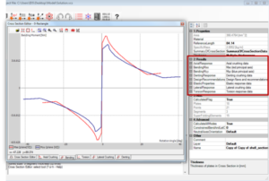
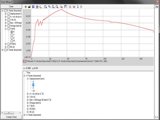
The computation time at the 2D level typically takes less than a fraction of a second on a standard PC. As a result, once the calculations are performed, user automatically receive outputs in several blocks along with basic plots representing axial, bending, and torsion responses. If needed, the output scope can be extended to obtain additional parameters and plots by making the appropriate settings.
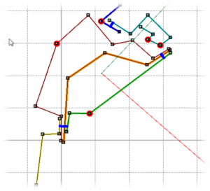
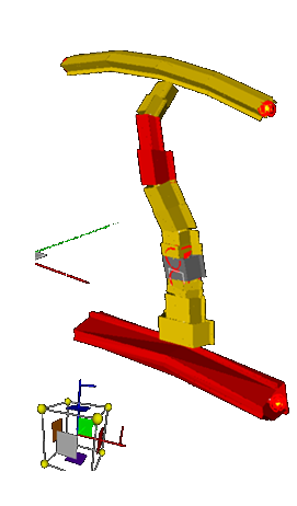
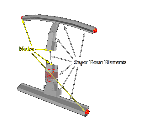 On the level of a 3D structure, the MEM allows the definition of a simplified B-Pillar beam model built of spatial objects (Nodes, Super Beam Elements), consequently testing various geometrical and material specifications in many configurations. The modeling procedure can be conducted semi-automatically based on the geometry imported, e.g., from the FE solution. The initial and boundary conditions are defined as kinematic constraints assigned to the nodes. The VCS enables crash analysis of structures with rigid bodies and deformable barriers such as the ODB or the IIHS side-impact barrier.
The presented B-Pillar structure consists of 11 cross-sections, 14 Nodes, and 13 SuperBeam Elements.
In the case of the presented load case (350 ms of simulation time, 87 500 time steps), calculations take only 6 seconds.
On the level of a 3D structure, the MEM allows the definition of a simplified B-Pillar beam model built of spatial objects (Nodes, Super Beam Elements), consequently testing various geometrical and material specifications in many configurations. The modeling procedure can be conducted semi-automatically based on the geometry imported, e.g., from the FE solution. The initial and boundary conditions are defined as kinematic constraints assigned to the nodes. The VCS enables crash analysis of structures with rigid bodies and deformable barriers such as the ODB or the IIHS side-impact barrier.
The presented B-Pillar structure consists of 11 cross-sections, 14 Nodes, and 13 SuperBeam Elements.
In the case of the presented load case (350 ms of simulation time, 87 500 time steps), calculations take only 6 seconds.
Please visit the (VCS – manual) section for detailed information about using Visual Crash Studio.
Please visit (VCS – tutorial) section for additional training resources, use cases and tips on the capabilities of Visual Crash Studio.